The burner wall: why a different material belongs here
The most heavily loaded surface in a furnace is not the one with the highest average temperature, but the one with the steepest swing. The flame bears on the burner wall — and the lining has to withstand there what no longer occurs ten centimetres away.
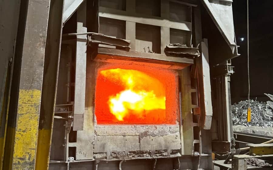
The flame bears on the burner wall. That sounds obvious, but it changes everything: this surface is not loaded by the average furnace temperature, but by radiation from a flame meeting a limited zone at a narrow angle. Ten centimetres away, conditions are different.
That makes the burner wall the zone where a lining most often fails first — and the zone where choosing material from a catalogue costs most. Line the whole chamber in one quality and you either under-specify it for the burner surround or over-specify it for everything else.
What comes together on this wall
Individually, none of it is unusual. That all of it occurs on the same surface is.
Radiation at close range. The flame does not heat the wall through the gas, it heats it directly. Where it bears, the surface temperature is higher than the furnace chamber reading suggests.
Temperature swings with every burner cycle. Each switch on and off creates a jump in the same place. It is not peak temperature that breaks a lining, but the number of cycles.
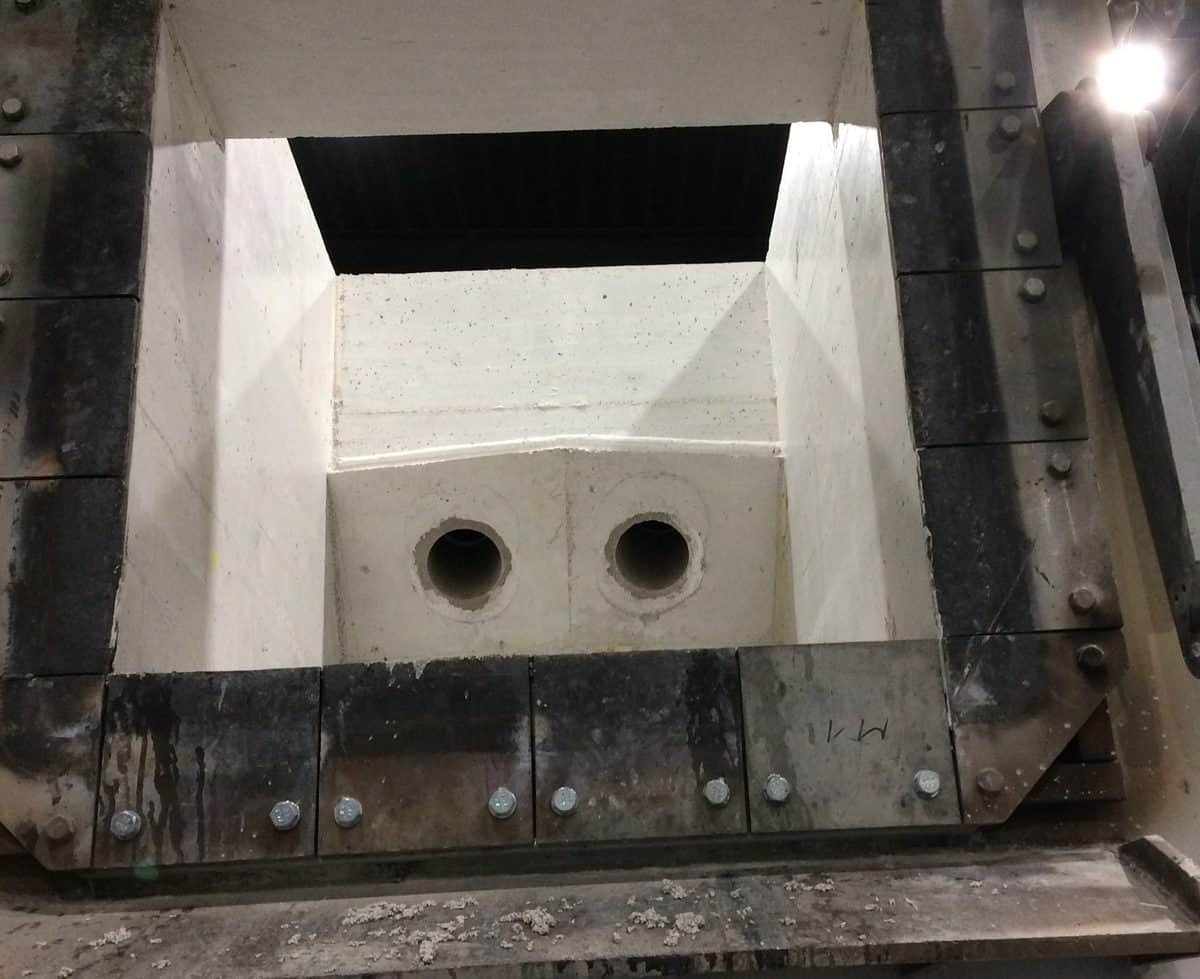
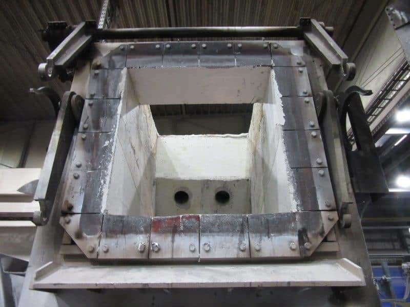
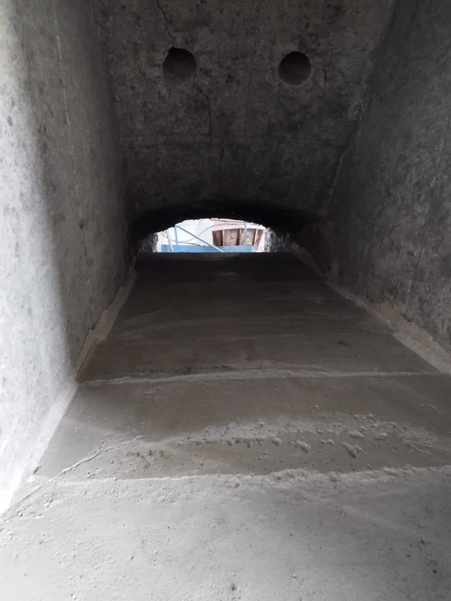
Openings as a geometric weakness. Every burner pipe is a hole in a load-bearing surface. Around the opening, expansion runs differently than in the free wall — and that is exactly where the hottest zone sits.
Mechanical impact during burner changes. Burners are pulled, checked, refitted. Every time, someone works with tools at the edge of the opening.
This explains why a burner wall often comes due long before the rest of the chamber — and why a partial repair is more defensible here than elsewhere: the damaged zone is clearly bounded.
The evidence is written on the wall
Before any work, we read the old wall. It shows where the flame actually bore — and that is not always where the design intended.
Soot and deposits. Dark edges around the opening indicate incomplete combustion close to the wall. That points to burner settings, not to the material.
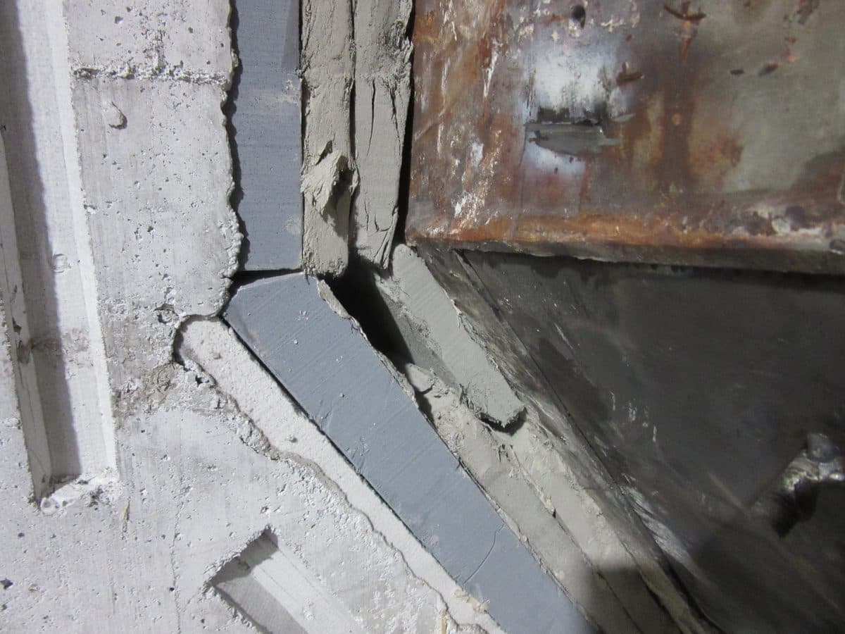
Washed-out edges. Where the surface has receded, the flame has worked on it across the campaign. The shape of the washed-out zone reveals the angle of attack.
Crack networks in the surround. Fine cracks closing into a network are the stage before a layer spalls off in one piece.
Exposed anchors. Once steel is visible, the cover is gone. From then on the anchor scales, and the castable is held by friction.
What the evidence does not say, the operator has to supply: operating mode, cycling, burner output. A wall that is back after two campaigns rarely has a material problem.
Build it from the outside in
A burner wall is not patched, it is built up — in order, starting from the steel.
Demolition down to the furnace shell. Not down to a residual layer that looks sound, but down to the steel. Old layers beneath new castable are the most common reason a wall spalls off in one piece after a short time.
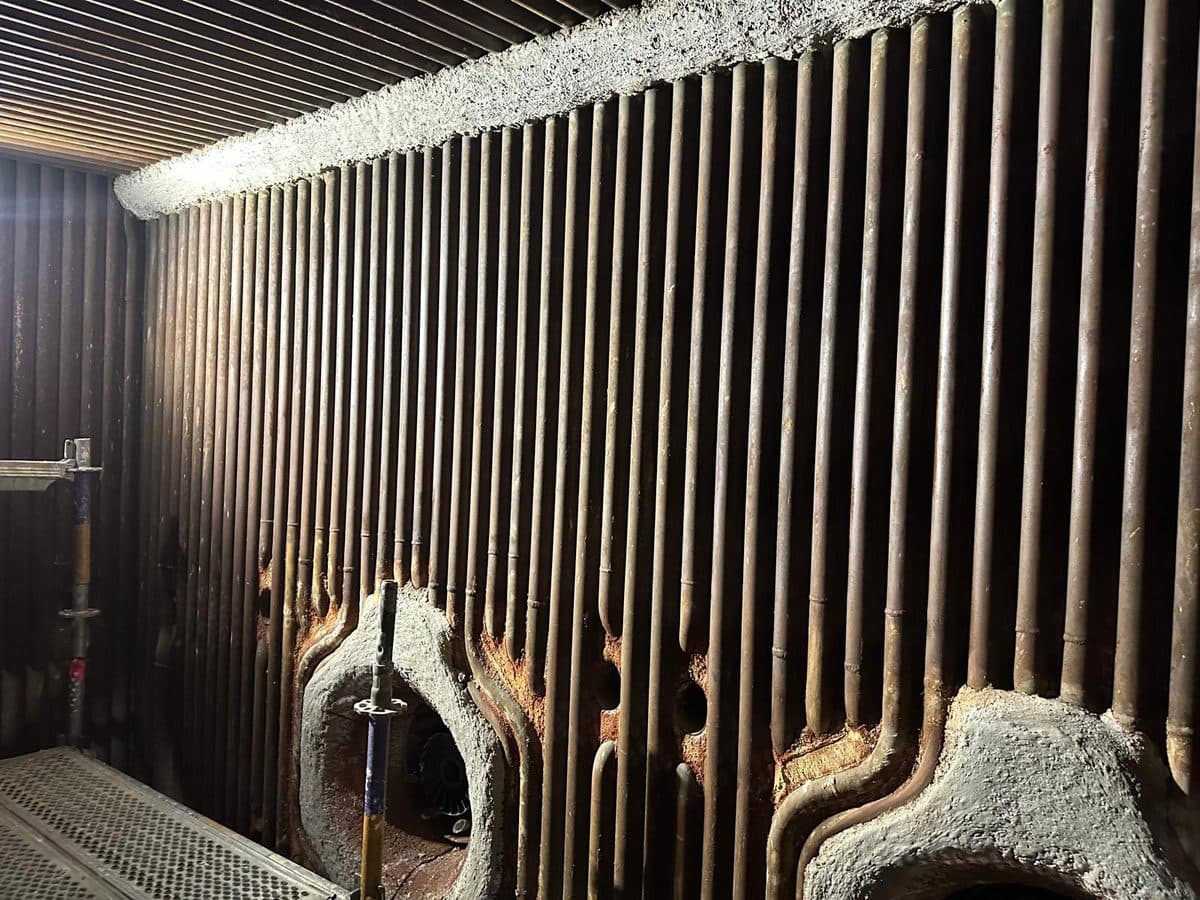
Ceramic fibre as the insulating layer. It limits heat flow into the shell and absorbs expansion. Its thickness is a design decision, not a fill quantity.
Anchors in a tight grid around the burner pipes. Where expansion runs around the opening, anchoring is denser than in the free wall. Material and spacing both decide service life.
Formwork and casting in one pour. Where a joint is unavoidable, it sits outside the burner surround — not wherever the formwork happens to end.
The order is not a formality. Each layer assumes the one beneath it is true to dimension: an uneven insulating layer produces a working layer of uneven thickness, and uneven thickness means uneven expansion.
Material by zone, not by chamber
Around the burners we install a thermal-shock-resistant castable — not the same one as in the rest of the chamber. This is where linings cost money in both directions: a uniformly high-grade lining is also paid for where it adds nothing. A uniformly simple one fails where failure gets expensive.
Where the geometry allows, the burner surround is produced as a prefabricated component in the workshop: cast under control, dried under control, inspected — and merely set in place on site. That shortens the shutdown and takes drying off the critical path.
What this lets you plan
The burner wall is the zone where a look during shutdown pays off fastest. It can be seen from the opening, the evidence is unambiguous, and the choice between repair and renewal is made on a clearly bounded surface rather than on the whole chamber.
If you can only walk one zone systematically at the next inspection, make it this one — and look at the edges of the openings, not at the wall.
At a glance
Radiation
heats the wall directly, not through the gas
Every cycle
a temperature jump in the same place
Down to the shell
demolition with no residual layer, or the lining spalls
Zone, not chamber
thermal-shock-resistant castable only around the burners
We use cookies and similar technologies to ensure that our website functions properly and to analyse how our content is used. In the settings you can choose which cookies you wish to allow. Privacy policy

 PDFMulti-chamber furnaces