
Zone-Correct Relining of a Biomass Combustion Chamber
Three zones, three demands — the right material in every place

Initial situation
In the combustion chamber of a biomass CHP plant with a moving-grate furnace, the lining had reached the end of its service life: the fuel bed had ground down the brickwork above the grate, transitions and expansion joints were worn, and the structure around the secondary-air nozzles was damaged. The operator commissioned SBS Refractory Service with a zone-correct relining within the planned outage.
Scope of services
- Survey of findings and measurement of the nozzle positions
- Demolition of the worn lining
- Brickwork above the grate, monolithic lining above it
- Stepped interlocking transition, expansion joints packed with ceramic fibre
- Handover with a written heat-up curve
Project data
The task
Three completely different demands in one space: mechanical abrasion above the grate, peak temperature and turbulence in the secondary-air zone, alkali attack at the boiler inlet
The transition between brickwork and monolithic lining must not form a continuous weak point
The position of the secondary-air nozzles had to be preserved exactly — it is part of the combustion design and determines burnout
A tight outage window: demolition, rebuild and controlled heat-up within the planned period
The SBS approach
Above the grate, a tight stretcher bond of fired firebrick was laid — with narrow joints where the fuel bed rubs against the wall with every stroke. Above it follows the monolithic lining, which forms corners, slopes and penetrations seamlessly in one pour.
The boundary between the two constructions was interlocked in steps, each step offset from the next — a crack that follows one step ends at the next. The expansion joints run vertically throughout and were packed with ceramic fibre instead of being filled with mortar. The secondary-air nozzles were surveyed before demolition and restored to the millimetre during installation.
At the boiler inlet, where the flue gases cool and the alkalis condense, a high-alumina material was used. Handover included a written heat-up curve so the mixing water of the monolithic zones can escape in a controlled way.
Zone-Correct Relining of a Biomass Combustion Chamber in pictures
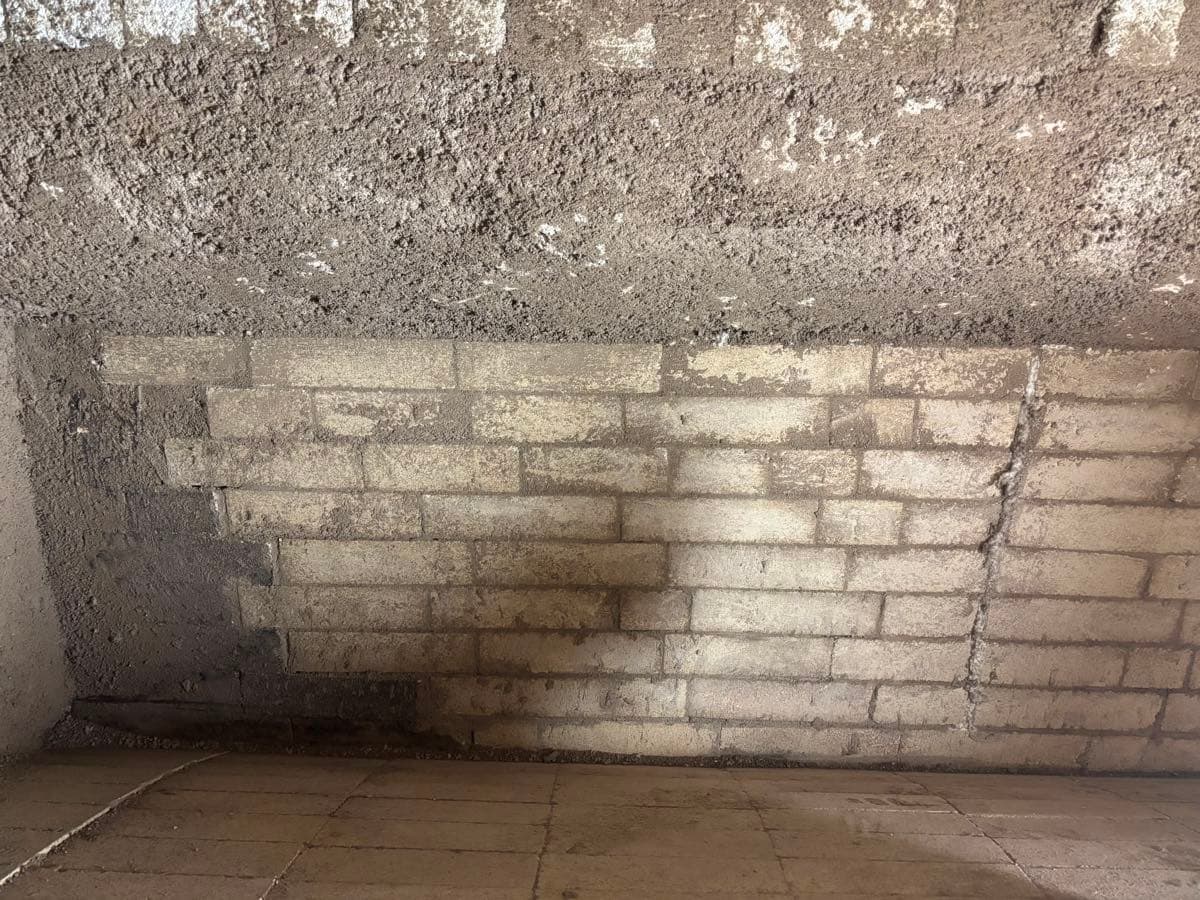
The boundary runs in steps, not straight — on the right, the continuous expansion joint
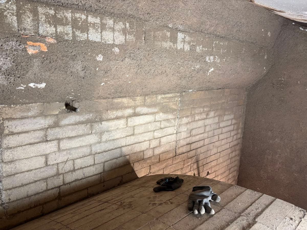
A tight stretcher bond with narrow joints where the fuel bed rubs against the wall
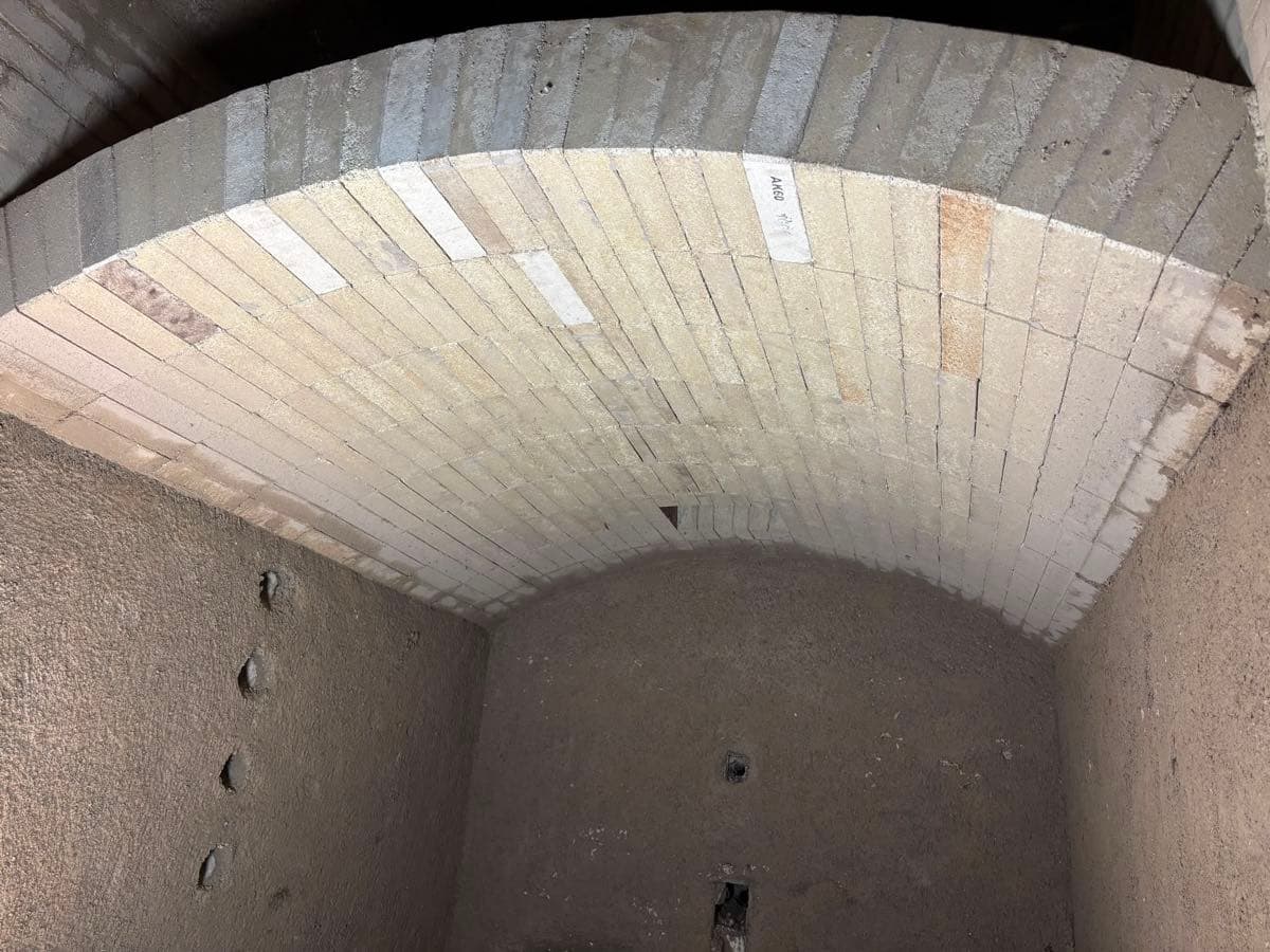
The vault back in brick: arch bricks in bond, below them the seamless monolithic wall
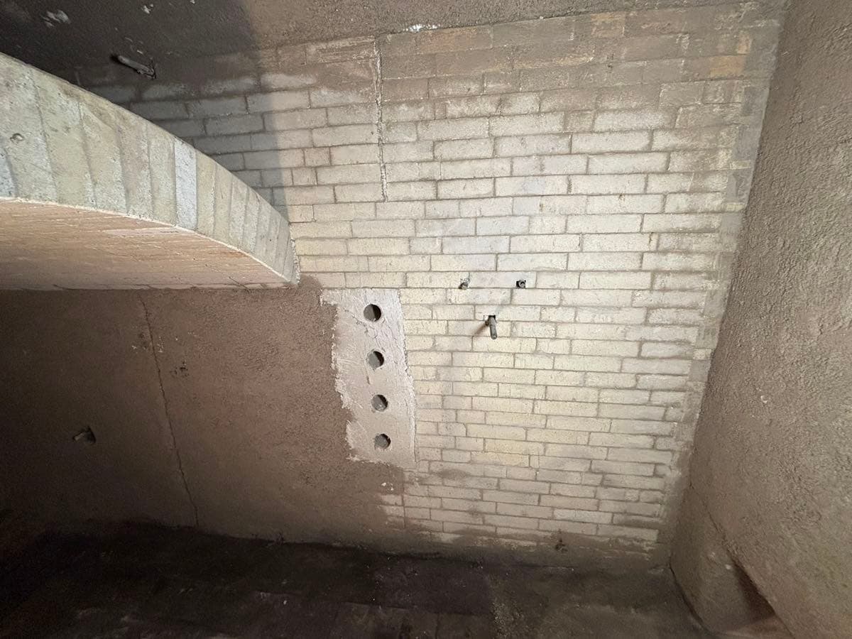
Set during installation and restored to the millimetre — not drilled afterwards
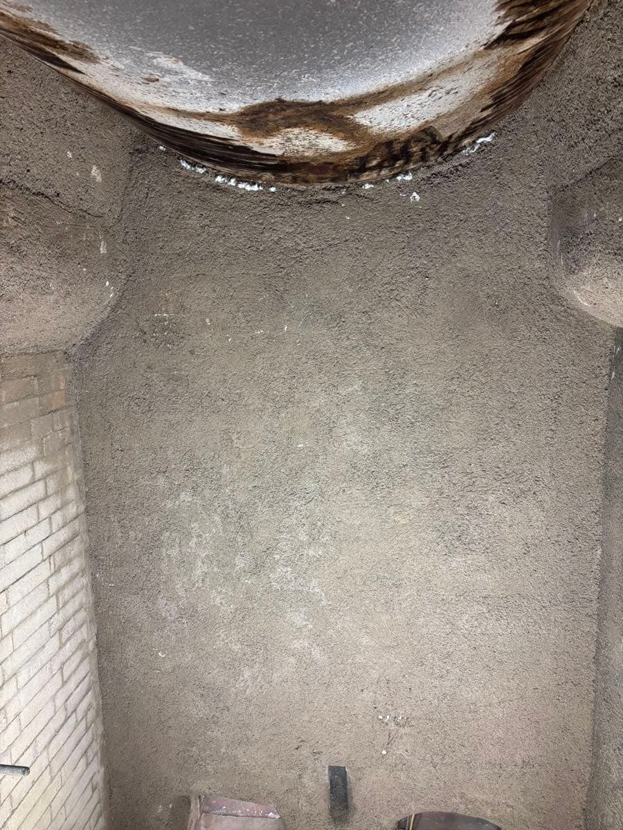
At the boiler inlet the alkalis deposit — high-alumina material stands here
Measurable results
The key figures of the “Zone-Correct Relining of a Biomass Combustion Chamber” project
Similar references
Planning a project?
Whether complete relining, repair or emergency — free initial consultation and a fast response.