
Test furnaces: when the lining measures too
Here the lining does not just hold — it measures
Initial situation
A fire test furnace determines how long a component withstands a fire. To do that it follows a standardised temperature curve, and how closely it follows depends not only on the burners but on the wall behind them. In 2026 SBS Refractory Service carried out the overhaul of two such test furnaces at a manufacturer of fire-resistant glass — a small one and a large one. Both were worn at the same places: where the geometry is interrupted.
Scope of services
- Special castable
- Insulating firebricks
- Insulating layer
- Anchoring
- Dry-out curve
Project data
The task
A heavy, dense lining would last longer — and would make the standard curve sluggish. Every kilogram that has to be heated as well distorts the measurement.
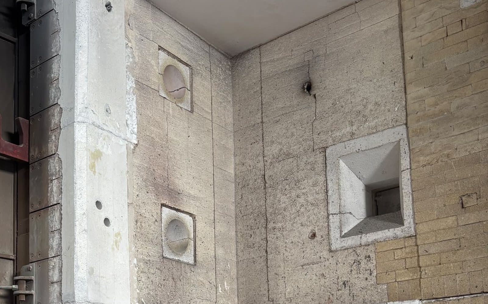
The viewing windows are disturbances in the wall build-up: the splay stands at an angle in the radiation field and takes the full thermal shock at every test.
The pillars carry load and at the same time stand free in the furnace chamber — they are stressed from more sides than a wall.
The exact scope only shows once the furnace is broken out; a fixed price on suspicion would have been guesswork.
The SBS approach
Viewing windows and pillars were broken out and recast in two-component special castable. A splay that defines the viewing angle and the seal can be produced more accurately cast than bricked — and has no joints for thermal shock to attack.
The lower fields of the large furnace are built with insulating firebricks, group 26. Low bulk density means low heat storage: the furnace follows the curve instead of heating against its own mass.
Insulating layer and anchors were renewed completely — not just the visible layer. New material over old, embrittled insulation puts the same spot back on the schedule in two years.
Behind the hot face lie a ceramic fibre blanket, microporous boards and calcium silicate. The staggering keeps the shell cool without building up thickness — in a test furnace every centimetre of wall is a centimetre less test space.
A dry-out curve with holding times was part of the lining work. The dry-out itself was carried out by the operator with their own control system.
Test furnace · Wall build-up
Four layers, of which you only ever see one.
Once the furnace has been heated up, a furnace wall shows only the working layer. Behind it lie three more layers that decide just as much about energy consumption and service life. The cut-out shows them one behind the other — along with the staggered joints in the brickwork and the anchors that pierce every insulating layer. Turn the model and look at the cut edge.
- Working layer
- approx. 250 mm
- Ceramic fibre blanket
- 13 mm
- Microporous boards
- 25 mm
- Calcium silicate boards
- 25 mm
- Anchor spacing
- 200–300 mm
The three insulating layers and the anchor spacing are dimensions from this project. The working layer is an order of magnitude. A test furnace is deliberately built slim — in a melting furnace the insulation is considerably thicker.
Modell wird geladen …
Ziehen zum Drehen · Scrollen zum Hineinschauen
Test furnaces: when the lining measures too in pictures
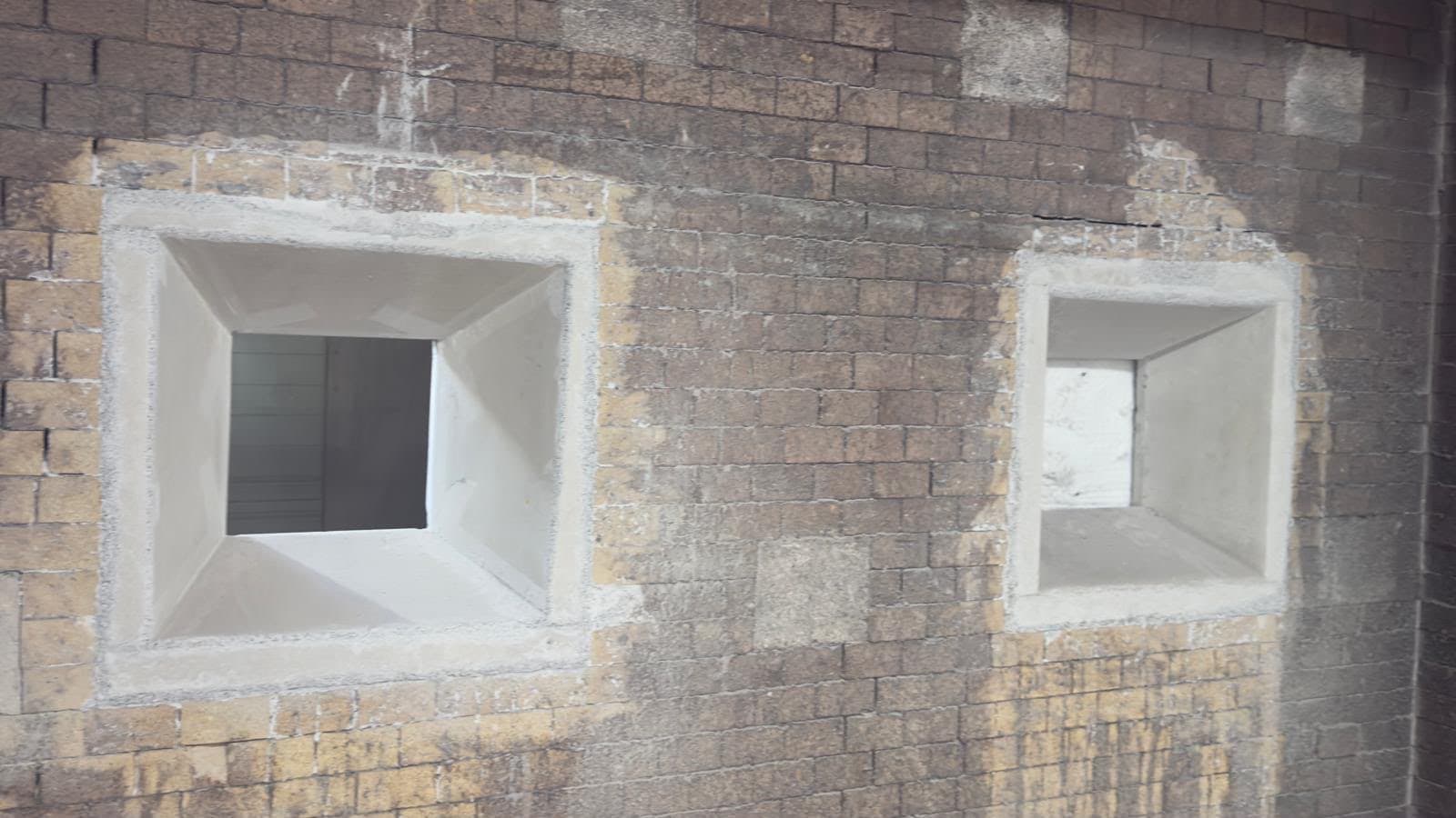
Two newly cast viewing windows in the retained brickwork
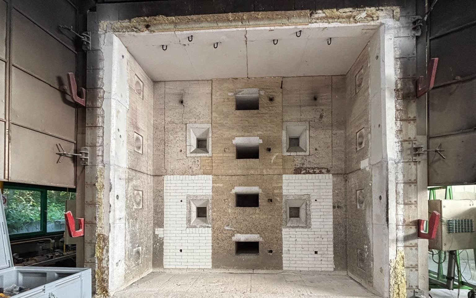
Opened test chamber: burner ports and the lower fields
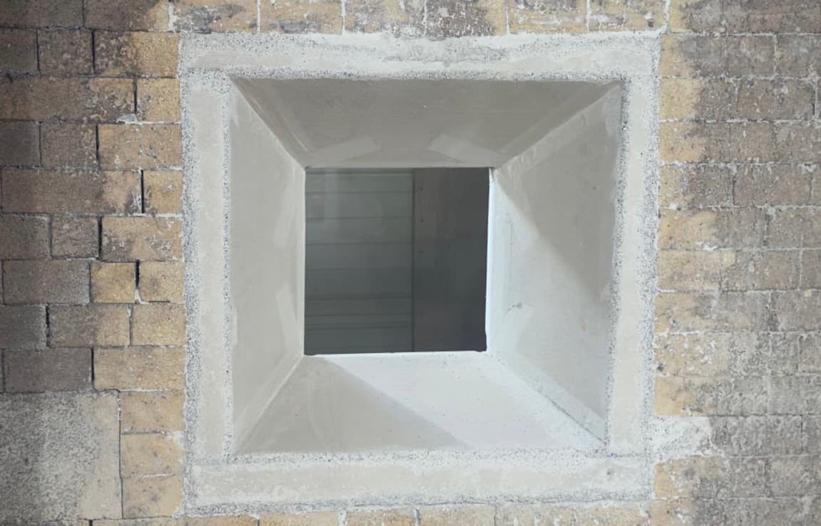
The splay defines viewing angle and seal — cast, not bricked
Measurable results
The key figures of the “Test furnaces: when the lining measures too” project
Similar references
Planning a project?
Whether complete relining, repair or emergency — free initial consultation and a fast response.